 By Shadow 7
Not too often will you see a co-phased antenna system on someone’s house. Especially now –a-days since everyone is either using a cell phone or using the free IM’s w/a mic/cam for communications but in the yesteryear radio world, why would anyone want
to put up a co-phased antenna system? Because he wants 3Db more of gain.
Right off that bat, the only stations that I knew that put up stacked arrays were Smiley Base (Chick-A-Dee – KCR-3112 – stacked 3’s), “City Boy” (Bobby Heater – KMD-7379 stacked 3’s), “Sunny D” from Lincoln Park – stacked 5’s for a short time), and myself – stacked 5’s.
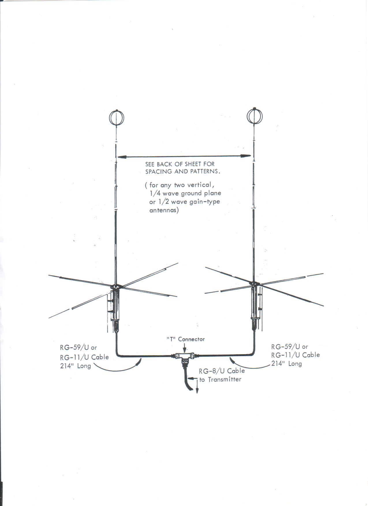
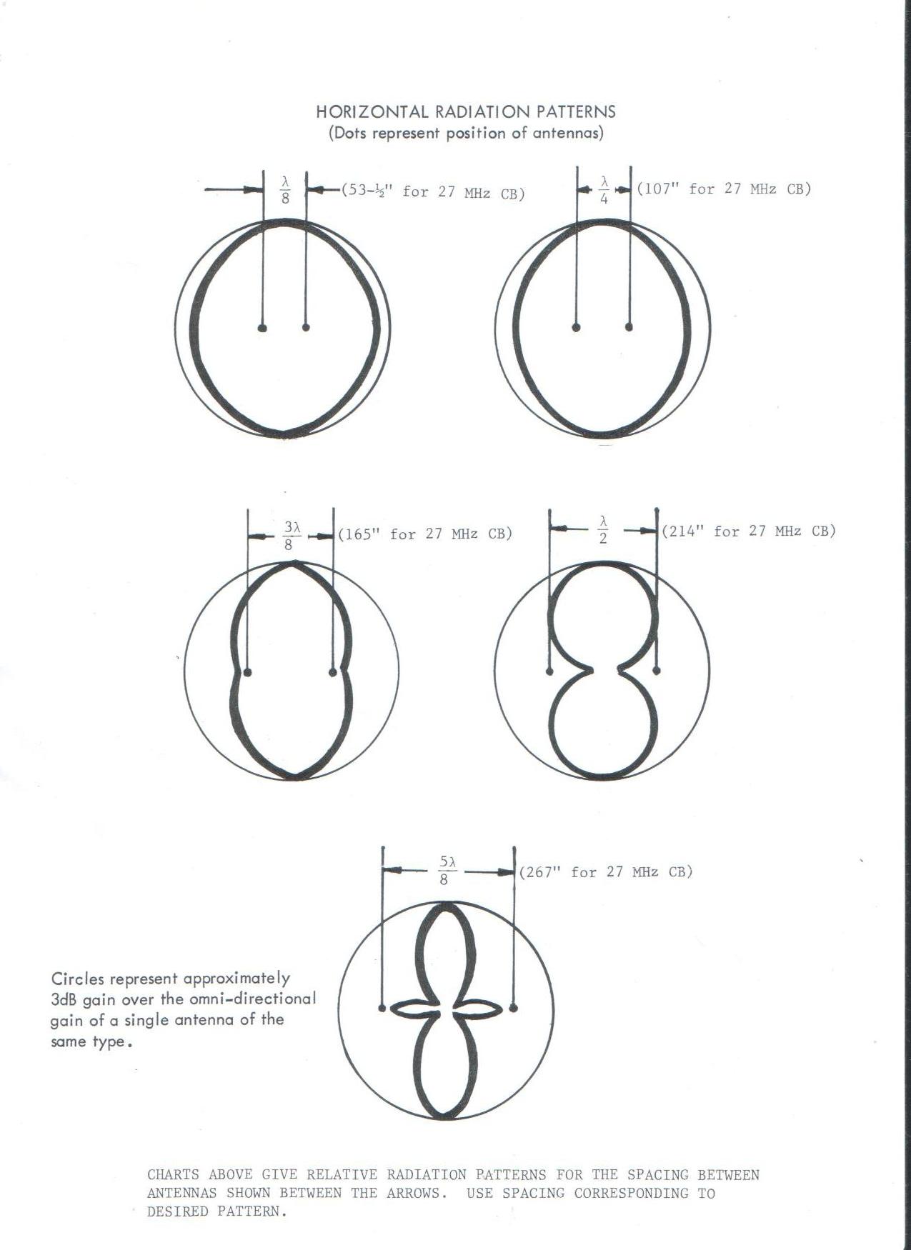
You can co-phase any (2) ½ wave ground plan antennas or 2 Yagi beams. These are normally called “co-phased” or “stacked” antennas. A stacked array will give you twice the power/gain (+3Db) if done right. Your TX and RX will both go up. You could say it’s a way the FCC can’t say or do anything being that you’re legally putting out 4 watts but yet the effective radiated power is 8 watts (+3Db).
FORWARD:
Have you ever wondered what would happen if you took your friends mobile antenna and placed it close to yours to see what will happen? If another metal pole, metal rod, etc, of almost equal length, comes in the vicinity of your antenna, the radiation pattern & SWR will change. Depending on the length and how close that 2nd element is to your antenna, determines if that 2nd element will act as a reflector or a director and also dictates how much of a change in the radiation and directional pattern. In a 2 element beam, the reflector is spaced a certain distance from the main radiator and its length of that reflector element is 5% longer than the main radiator (driven element). The 2 element beam is 25% directional. If done right w/your mobile antennas, you can also increase your mobile signal by 25% in a certain direction.
NOTE: This documentary will not apply to the “Scanner” or “Super Scanner” which has its own system of beam operation. This system uses a separate coax switch box at the antenna and has a control box at the transceiver. This antenna used 3 vertical elements spaced evenly apart from each other in a 120 degree pattern. The Scanner and the Super Scanner worked well but it lacks the ability to point a signal in between the 120 degree pattern of its operation, where a beam can.
In this documentary, we will be dealing with impedance matching, spacing, and radiation patterns. Impedance matching is necessary since the industry standard of transmitters is 50 ohms unbalanced coaxial transmission line.
Since we’re getting into impedance, we might as well get into some things about coax. In a coax, you have a shielded cable around a center conductor. The center conductor is placed concentrically. The outer shield must maintain the same distance from the center conductor throughout its 360 degree. If a coax didn’t have a dielectric to hold the center conductor in place, but yet, the center conductor was somehow, held in place, we could call this “free space”. Calculations in free space are different than the calculations where a dielectric is used to hold the center conductor in place.
The dielectric material used, varies from manufacturer to manufacturer. These materials are called dielectrics since they do not conduct electricity. There is a capacitance between the center conductor and shield, whether we use a dielectric or not. Regardless, there is a capacitance and therefore, a dielectric constant. This constant must be used in the formula since the dielectric changes the wavelength electrically.
Calculations are based upon propagation of an RF coax as opposed to free space; therefore, it involves formulas used to calculate a free space wavelength at a specific frequency, which are acted upon in accordance with the velocity of propagation in a coax most suited for the job of impedance matching. In all practical situations (not in free space or a vacuum) the velocity of propagation will be less than 100%, which will result in a length shorter than a free space wave length or a fraction thereof..
The formula for determining the wavelength in free space (or in the presence of a vacuum between the center conductor and shield) is: 984/freq = length in feet or 11808/freq = length in inches.
Therefore, using channel 20 as the center of the band, 984/27.205Mhz = 36.16’.
The formula for determining the wavelength using a dielectric such as polyethylene (which has a dielectric constant of 65.9%) is 984 X .659/27.205 = 28.83’. As you can see, there is a big difference in accounting for the dielectric constant when determining a wavelength. The presence of a dielectric between the center conductor and the shield, loaded the length of the line and physically shortened it; but electrically, it remained one wavelength. With these calculations, we can derive “phasing sections” or “Q sections”. The same applies to the calculations to the phasing sections made from coax and makes it convenient to use coax for phasing 2 antennas in a 50 ohm unbalanced system.
There are 2 ways you can co-phase antennas. You can buy a power divider or you can do the “T” connector method as I did w/my own stacked 5’s.
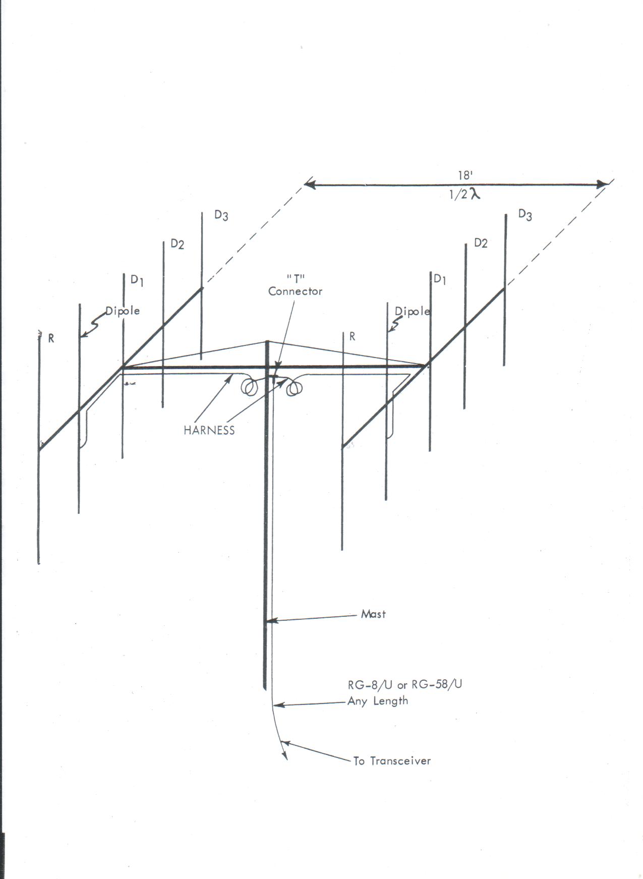
Co-phased system using a “T” connector:
If you choose to do the “T” connector method, you will have get a “T” connector where all 3 ends are female. You will also have to make a co-phasing harness. This means that you will have to make 2 coax cables, both coming out of the “T” connector, going to each antenna. They must be exactly the same length physically & electrically. Measuring them physically may not be enough. A network analyzer would come in handy at this point. These coax’s to be made are not 50 ohm coax. See Co-phasing harness coax formula for type of coax to be used (below).
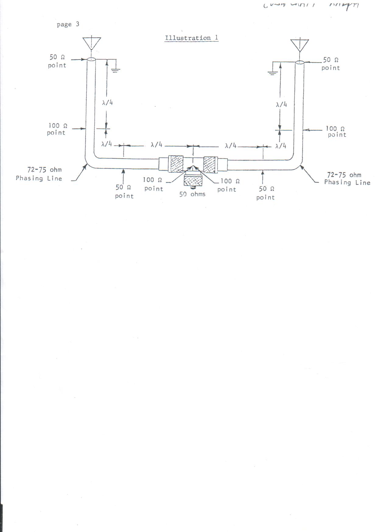
In a co-phased harness, impedance repeats itself every ½ wavelength. After the first ¼ wavelength, impedance doubles itself and repeats itself every ½ wavelength. The pattern would look like this – 50 ohms, 100 ohms, 50 ohms, 100 ohms, and so on.
From this, we can put 2 antennas in parallel where they join to the “T” connector. At this point, both coaxes will be 100 ohms. 2 100 ohm antennas in parallel brings your impedance back to 50 ohms going down to your transmitter.
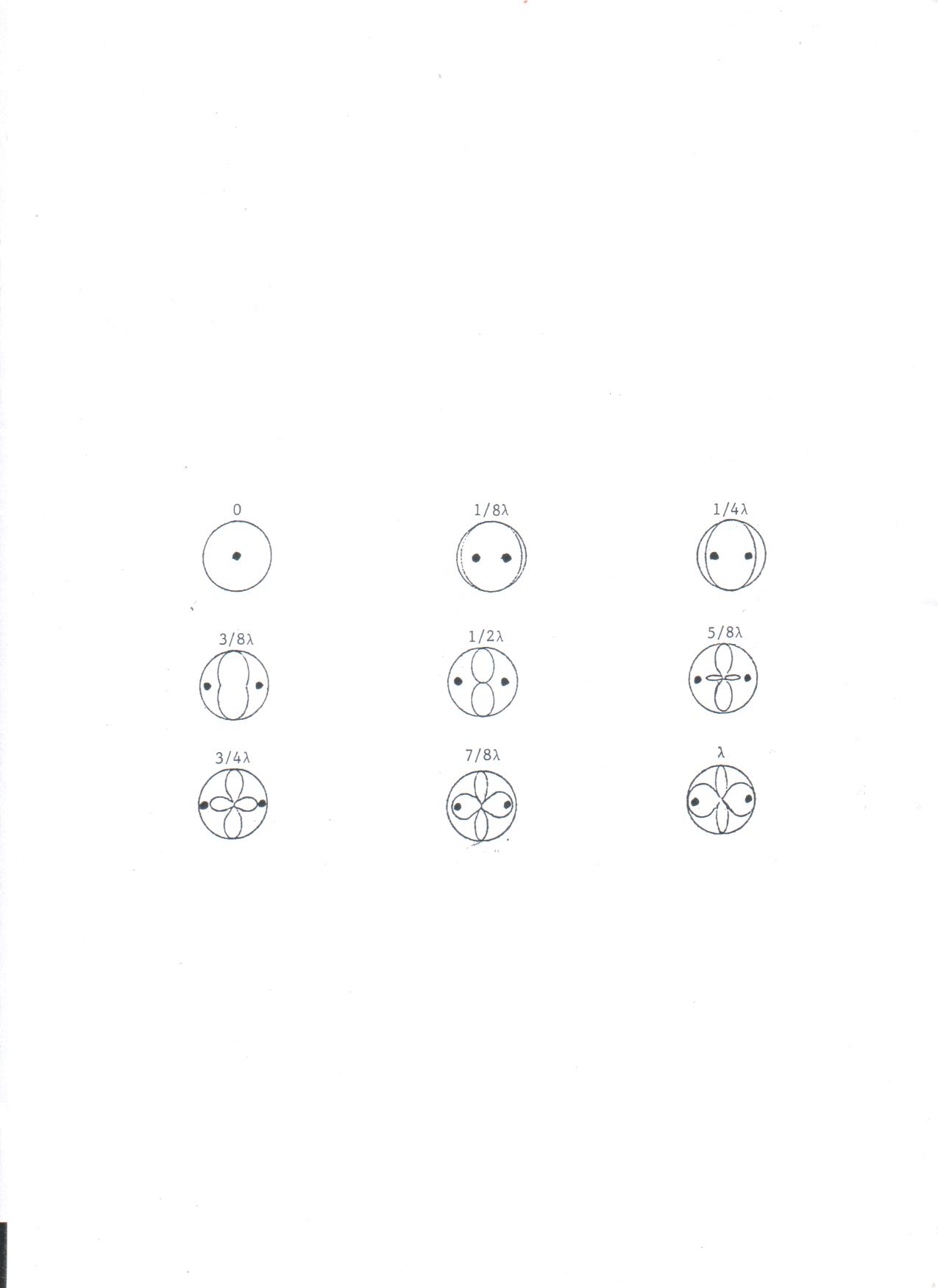
Space the antennas for the radiation pattern desired. Your antenna gain will increase depending on the pattern desired. Even though both antennas are driven elements, they will act as reflectors to each other..
If we were going to put up stacked antennas, one must decide on what freq one will use to calculate on. Usually the center of the band is a good start. Also, select what radiation pattern desired. The lengths of the coax harness must be long enough to reach each antenna per that spacing.
Co-phasing harness coax formula:
2952 * coax dielectric constant / Freq = 1st Q section (Lambda). The usual dielectric constant for coax is 66%. Check w/the manufacturer.
2952 * .66 / Freq = 71.61”
71.61” is your 1st Q section. (71.61” / 12” = 5.96’)
2952 * .66 / 27.205 = 71.61”. Our first Q section is 71.61”. Each coax coming out from the “T” connector is 71.61”. At this point, you can attach both antennas to the ends of these coaxes if this is the radiation pattern you desire. Since you have these 2 antennas in parallel, your total impedance is now 50 ohms. The only question is, is this the radiation pattern you desire? If so, you’re done. If not, you’re not done.
According to the radiation pattern for the best forward gain and best side rejection, ½ wave is used. For ½ wave, use a spacing boom of 18’. This will separate the antennas 9’ out in both directions from the main vertical mast. For ½ wave spacing of the 2 antennas, the length of the coaxes for a 1st Q section is physically not long enough. Since impedance repeats itself at every 1/2 wavelength, your next option is to choose the next odd multiple of Q section -3rd multiple. You can not choose a 2nd multiple as both coaxes impedance will be 50 ohms at the “T” connector. 2 50 ohm antennas in parallel will have a feed point impedance of 25 ohms at the “T” connector. This is a mismatch and will be noticed on the SWR meter and a receivers “S” meter and negate the purpose of stacking antennas. Your next choice is to select a 3rd multiple as this may be long enough to reach both antennas.
For the 3rd multiple - 71.61 * 3 = 214.8” (17.9’)
214.8” / 12 = 17.9’ per coax
The length of your coax harness at the 3rd multiple is 17.9’. This is more than enough since the distance from the T connector to each antenna is 9’ (108”). The coax harness length, if you used the 1st Q section would be 5.96’ (71.61”) which will not be long enough for ½ wave length spacing. Since your coax harness lengths are longer than necessary, coil up the excess coax in coils no smaller than 12” diameter and tape it closest to the center of the boom where the vertical mast joins with the horizontal boom. Keep it away from the antennas as you don’t want any metal close to the antennas which will cause a reflection, change the radiation pattern, and the SWR of the antennas.
The same above applies for stacked 3’s, 4’s, 5’s, etc. It’s a good idea to space the antennas ½ wavelength apart for the forward gain and also the side rejection. If a certain type radiation pattern is desired where the spacing between both antennas is a greater distance of ½ wave, you may need to go the 5th multiple. Thus, 71.61 * 5 = 358.05” / 12 = 29.84’.
Since the impedance in the phasing harness is changing from 50 to 100 ohms at every ¼ lambda, we need to select a coax that is closest to the 2 impedances of 50 and 100 ohms. The formula for this is:
Sq root of 50 * 100
R1 50 ohms * R2 100 ohms = 5000
Sq root of 5000 = 70.7 ohms
You have a choice of coax thickness’s to choose from. You can use RG-59/U (75 ohms) which is mostly used in CCTV or you can use the thicker RG-11/A which has a lower loss. The RG-11/U is close to the 2 impedances above and can withstand a higher power than the mobile coax. This is ideal as you want to keep the highest gain possible.
After you make these coaxes as equal length as possible for whatever multiple needed, then solder on your PL-259’s at both ends.
As far as running the main coax from the rig to the “T” connector, you can use RG-8/U, RG-8A/U, RG-213 (better) or 9913 (better yet). I wouldn’t recommend using RG-58/U (mobile coax). Some of the extra gain achieved by co-phasing antennas will be lost through this coax. The attenuation and insertion loss of this coax is higher and will partially negate the purpose of putting up a stacked array.
Theory:
GROUND PLANE:
How does a co-phased antennas work? Let’s start off learning first how a ground plane antenna works
Let's start with the operation of a 1/2 wave dipole. The radiation pattern of a vertical dipole is a 360 degree pattern around the main radiator. Its counterpoise is the lower half of the antenna (ground). You can visualize this as a wide horizontal donut where the radiator element is centered in the middle of the donut hole. RF goes out of the radiator (top) evenly in a 360 degree vertical pattern (top of the donut), and returns back to the bottom part of the donut. The dispersion angle of radiation is not completely focused at the horizontal plane. The majority of the pattern is slightly higher above the horizon. Some manufacturers of ground plane antennas have installed ground radials to help bend the RF more towards the horizon for better distance from counterpoise radiation.
When placing an identical antenna in close proximity to the other one, your radiation pattern starts to change. Your SWR will change also. When the 2 main radiators are placed at a specific calculated distance from each other, the total gain of the system increases and develops a new radiation pattern off to both sides.
BEAM:
2 Element Beam – There are 2 elements in a 2 element beam. The driven element and the director element. The length of the 2nd element is 5% shorter than the driven element. This is a DIRECTOR element. The radiation pattern will increase by 25% in the direction from the main radiator towards the director.
There’s another way to make a 2 element beam. By placing an element in back of the driven element. This element is 5% longer than the driven element. This is a REFLECTOR element. The radiation pattern will increase by 25% in the direction from the reflector to the main radiator. In this particular set up, this is normally called a 2 element beam.
If both 2 element beams are spaced apart correctly and the proper co-phasing harness is used, this is called co-phased antennas or stacked 2’s.
Note: As you introduce a 2nd element, the 2nd element will cause a change in radiation pattern and SWR, as the impedance of the main radiator is shared w/the 2nd element and is now part of the system.
3 ELEMENT BEAM
Let's see how a single 3 element beam antenna works:
A 3 element beam has 3 elements - reflector, driven, & director elements, in this order. The coax is connected to the driven element only. The reflector element is spaced away from the driven element as is the director and they are in line.
The RF wants to radiates the driven element in a 360 pattern like a ground plane but since we have 2 other elements involved a directional pattern is created. The signal from the driven element reflects off the reflector and is attracted back to the driven element, then continues in that same direction towards the director. As we now have a line up of 3 elements, we have 3 circulating currents, we now have a direction pattern – a beam.
As the number of directors are increased, the direction pattern gets more narrower, therefore the gain increases and more rejection on the sides.
Beams are ½ wave.
NOTE: As a rule if thumb, do not put multiple antennas (of different operating frequency’s) close together as this will cause signal reflections, a radiation pattern change, and a bad SWR on all antennas. The excuse of “I didn’t have enough space.” is why you will have reflection, radiation, and SWR problems. Even the human body can change the radiation pattern and SWR if you’re too close to an antenna.
Let the antenna do its job. Let the antenna radiate and have its space as it should. This is especially important when co-phasing beams. The spacing is important to develop the radiation pattern you want. If space is a problem, try distancing your antennas of different operating freq’s a full wave apart from each other. Try to stay away from trees, buildings, wires, metal, etc. Trees contain water which can reflect or absorb your signal.
Come to think of it, I’ve have seen a few people try to “co-phase” 2 stainless steel whip antennas in the mobile, not spaced correctly, and no phasing harness. They just paralleled the 2 coax’s into the main coax line and called it “co-phased”
You will not benefit by soldering 2 antennas into a random coax line. Your SWR will go up to approx 3:1 (11% loss) or worse. Also, your coax impedance will drop to 25 ohms because you directly put 2 – 50 ohm antennas in parallel.
NOTES:
Polarization is the direction of the electric lines of force.
RF consists of 2 fields - a magnetic field and an electric field.
In a vertical polarization, the electric field is perpendicular to the earths surface. The magnetic field is parallel to the earths surface.
In a horizontal polarization, the electrical field is parallel to the earths surface. The magnetic field is perpendicular to the earths surface.
To make your own co-phased system, you will need the following items:
Main coax - RG-8/U, RG-213, or 9913.
Co-phasing harness coax – RG-11/U for the length needed per radiation pattern/Q sections
One “T” connector – all ends are female
One horizontal boom - strong enough to support 2 ground plane antennas at the distance needed for the radiation pattern required, or of schedule 80 or equivalent (1/4” wall thickness) for stacking beams.
Cross boom mount – This mounts the horizontal boom to the main vertical mast. You can cut a piece of 5/16” or 3/8” thick sheet aluminum the shape of a traffic stop sign, drill holes where the U-bolts will go. The main mast will bolt to one face with its U-bolts. The horizontal boom will mount on the other side of the mount with it’s own U-bolts. If you need an idea on how to make this, email me at KB2JXM@Yahoo.com. Please put “Cross boom mount” in the subject.
One Network analyzer – if you can borrow one
6 PL-259’s – 2 for the antennas (if the SO-239’s come with the antennas). Some beam manufactures have you strip back the coax a certain distance and physically screw or bolt the shield and center conductors right to the Beta match.
ASSEMBLY AND MOUNTING:
Build one antenna at a time. Solder a PL-259 to the ends of the main coax. Make sure it ohms out and has no shorts. Set the Beta match in accordance with the antenna directions for setting the initial SWR. After one beam or ground plane is completed, mount the antenna where it will be mounted on the house. Bear in mind that the higher the antenna will be mounted, the SWR will read truer and the antenna will radiate more on its own and not be shared with ground or any other metal structures around as this could cause unwanted reflection, RF absorption, and an untrue antenna SWR. The higher the antenna is mounted, the better you will “get out”. After the antenna is mounted, read the SWR. If the SWR reads bad, then you will have to re-adjust the Beta match or sometimes in extreme cases, the length of the driven element, for a good SWR. This can be an all day affair taking the antenna down again to re-adjust the SWR each time. A fairly good idea is to make a temp mounting device next to the house where you can adjust the SWR from the peak of the house. Once this is done, mount the antenna where it will be permanently. Check the SWR again and see if it changed much from the temp mounting device. If the SWR changed a lot from the temp mount, then you will have to mount the antenna on the house each time to check and re-adjust the SWR each time. I know it’s a pain as I’ve done this many times on many homes and yes, it does become a pain but its the best way. Adjust for the best SWR in the middle of the band. Don’t rely on an antenna tuner or a match box. Let the antenna radiate at resonance as it was designed and for the best possible gain. That’s why you bought a beam.
Build the 2nd antenna. Adjust the SWR the same way as above. Once both antennas are complete and both antennas are at their best SWR’s, install your co-phasing harness, “T” connector, main coax, and mount both antennas on the spacing boom, mount the spacing boom to the main mast, and mount it permanently on the highest spot on the house. Check the SWR. The SWR will now read for both antennas.